PET preform mold design steps list
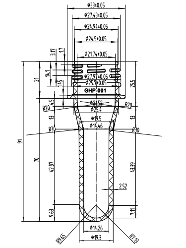
Step 1: Analyze 2D and 3D deawings
1. The geometric shape of the product
2. The size, tolerance and design
3. The technical requirements of the product (i.e. technical conditions)
4.The name, shrinkage and color of the plastic used in the product
5. The surface requirements of the product
Step 2: Injection Machine Size Choice
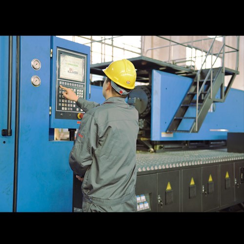
Injection machine is mainly based on the product size and production batch. When choosing injection machine, designers mainly consider the plasticizing rate, injection volume, clamping force, effective area for installing the mold (internal distance between the tie rods of the injection machine), capacity modulus, ejection form and fixed length. If the customer has provided the model or specification of the injection used, the designer must check its parameters. If the requirements cannot be met, he must discuss with the customer for replacement.
Step 3: Cavity Number Determination and its Arrangement
The number of cavities is mainly determined based on the following factors:
1. The production quantity (monthly batch or annual batch).
2. Whether the product has side core pulling and its treatment method.
3. Dimensions of the mold and the effective area of the injection molding installation mold (or the inner distance between the tie rods of the injection machine).
4. Preform weight and injection machine volume
5. The projected area and clamping force of the product.
6. Preform precision.
7. Preform color.
8. Economic benefits (production value of each PET Preform Mold).
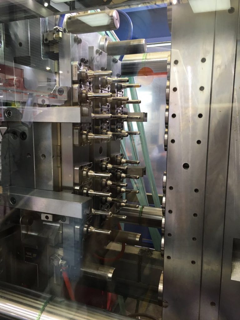
The above factors sometimes restrict each other, so when determining the design scheme, coordination must be carried out to ensure that the main conditions are met. After the number of strong characters is determined, the arrangement of the cavities and the layout of the positions of the cavities are carried out. The arrangement of the cavity involves the size of the mold, the design of the gating system, the balance of the gating system, the design of the core-pulling (slider) mechanism, the design of the insert core and the design of the hot runner system. The above problems are related to the selection of parting surface and gate position, so in the specific design process, necessary adjustments should be made to achieve the most perfect design.
Step 4: Determination of parting surface
- It does not affect the appearance of the preform
- Ensure the accuracy of the preform
- It is beneficial to mold processing, especially the processing of cavity.
- It is beneficial to the design of pouring system, exhaust system and cooling system.
- It is conducive to the demoulding of the product, ensuring that the product stays on the side of the moving mold when the mold is opened.
- It is convenient for metal inserts.
When designing the lateral parting mechanism, it should be ensured safe and reliable, and try to avoid interference with the setting mechanism, otherwise a pre-returning mechanism should be installed on the mold.
Step 6: Determination of Mold Base and Selection of Standard Parts
When designing the mold base, select the standard type as much as possible, and determine the form, specification and thickness of the A and B plates. Standard parts include general standard parts and mold-specific standard parts. Common standard parts such as fasteners, etc. Standard parts for molds, such as positioning rings, sprue sleeves, push rods, push tubes, guide posts, guide sleeves, special springs for molds, cooling and heating elements, secondary parting mechanisms, and standard components for precision positioning, etc. It should be emphasized that when designing molds, standard mold bases and standard parts should be selected as much as possible, because a large part of standard parts has been commercialized and can be bought in the market at any time, which is extremely important for shortening the manufacturing cycle and reducing manufacturing costs. advantageous. After the size of the buyer is determined, the necessary strength and rigidity calculations must be performed on the relevant parts of the mold to check whether the selected mold base is appropriate, especially for large molds.
Step 7: PET Preform Mold Pouring System Design
The design of the gating system includes the selection of the main channel, the determination of the cross-sectional shape and size of the runner. If a point gate is used, in order to ensure the detachment of the runner, attention should also be paid to the design of the de-gate device. When designing the gating system, the first step is to select the location of the gate. Whether the selection of the gate position is appropriate or not will directly affect the molding quality of the product and whether the injection process can be carried out smoothly. The selection of the gate position should follow the following principles:
1. The position of the gate should be selected on the parting surface as far as possible, so as to facilitate mold processing and gate cleaning.
2. The distance between the gate position and all parts of the cavity should be as consistent as possible, and the process should be the shortest (generally, it is difficult to do with large gates).
3. The position of the gate should ensure that when the plastic is injected into the cavity, it faces the spacious and thick-walled part of the cavity, so as to facilitate the flow of plastic.
4. Prevent the plastic from rushing directly to the cavity wall, core or insert when it flows into the cavity, so that the plastic can flow into all parts of the cavity as soon as possible, and avoid the deformation of the core or insert.
5. Try to avoid welding marks on the product. If it is to be produced, make the melting mark appear in the unimportant part of the product.
6. The position of the gate and the injection direction of the plastic should be such that the plastic can flow in evenly along the parallel direction of the cavity when it is injected into the cavity, and it is conducive to the discharge of gas in the cavity.
7. The gate should be designed on the part that is easiest to remove on the product, and at the same time, it should not affect the appearance of the product as much as possible.
Step 8: PET Preform Mold Ejection System Design
The ejection form of the product can be summarized into three categories: mechanical ejection, hydraulic ejection, and pneumatic ejection. Mechanical ejection is the last link in the injection molding process, and the quality of the ejection will ultimately determine the quality of the product. Therefore, the ejection of the product cannot be ignored. The following principles should be observed when designing the ejection system:
1. In order to prevent the product from being deformed due to ejection, the thrust point should be as close as possible to the core or the part that is difficult to demould, such as a slender hollow cylinder on the product, the push tube is often used to eject it. The arrangement of thrust points should be as balanced as possible.
2. The thrust point should act on the part of the product that can withstand the greatest force and the part with good rigidity, such as ribs, flanges, wall edges of shell-shaped products, etc.
3. Try to avoid the thrust point acting on the thinner surface of the product to prevent the top of the product from being white and high. For example, shell-shaped products and cylindrical products are mostly ejected by push plates.
4. Try to avoid the ejection marks from affecting the appearance of the product, and the ejector device should be installed on the hidden or non-decorative surface of the product. For transparent products, special attention should be paid to the selection of the position and ejection form.
5. In order to make the product evenly stressed when it is ejected, and to avoid deformation of the product due to vacuum adsorption, composite ejection or a special form of ejection system is often used, such as push rod, push plate or push rod, push tube composite Ejection, or use air intake push rods, push blocks and other fixed devices, and if necessary, an air intake valve should be installed.
Step 9: PET Preform Mold Cold System Design
- The arrangement of the cooling system and the specific form of the cooling system.
- Determine the specific location and size
- Cooling of key parts such as moving model cores or inserts.
- Cooling of side slider and side slider core.
- Design of cooling components and selection of cooling standard components.
- Design of sealing structure.
Step 10: Guiding Device
The guiding device on the plastic injection mold has been determined when the standard mold base is used. Under normal circumstances, designers only need to choose according to the mold base specifications. However, when a precision guide device must be set according to the product requirements, the designer must carry out a specific design according to the mold structure. The general guidance is divided into: the guidance between the movable and fixed molds; the guidance between the push plate and the push rod fixed plate; the guidance between the push plate rod and the movable template; Generally, due to the limitation of processing accuracy or the reduction of matching accuracy of the guide device after a period of use, it will directly affect the accuracy of the product. Therefore, for products with higher precision requirements, precision positioning components must be designed separately, and some have been standardized, such as cones. Locating pins, locating blocks, etc. are available, but some precision guiding and positioning devices must be specially designed according to the specific structure of the module.
Step 11: PET Preform Mold Material Choice
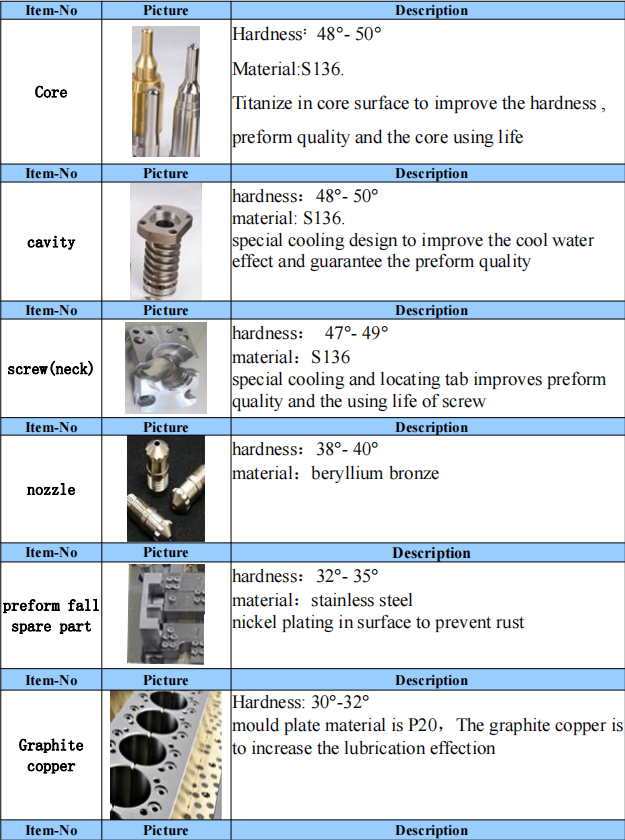
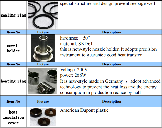
Winiber PET Preform mould material list
Winiber, Provides complete PET Preform Production Line. If you have such requirement, pls contact with us for the detailed quotation. Thank u!


I like assembling useful info, this post has got me even more info! .
I just could not leave your web site before suggesting that I really enjoyed the standard information a person supply to your visitors Is gonna be again steadily in order to check up on new posts
If some one wants expert view regarding blogging and site-building after
that i advise him/her to pay a visit this weblog, Keep up the fastidious
work.
Can I just say what a relief to find somebody that actually knows what they’re talking about on the internet.
You actually know how to bring an issue to light and make it important.
More people must check this out and understand this side of the story.
It’s surprising you aren’t more popular given that you certainly
possess the gift.
Hello! I just want to offer you a huge thumbs up for the excellent information you have got here on this
post. I will be returning to your website for more soon.
The Writing is like a warm fireplace on a cold day, inviting me to settle in and stay awhile.
Every article you write is like a new adventure. I’m always excited to see where you’ll take me next.